With the subdivision of the car function, the appearance and function of the axle housing are also diverse, and the variety of the axle housing of the chassis manufacturer is more and more, which requires the processing equipment to have certain flexibility and is suitable for small and medium batch production. A certain type of disc brake heavy-duty vehicle axle is shown in Figure 1. The outer circle, the outer cone surface, the flange end surface and the external thread are to be machined. At the same time, it is required to process the hole on the flange end face and ensure the process diagram. Various dimensions, geometric tolerances and surface roughness requirements are shown. Since the flanges need to be equipped with disc brakes, the six through holes for mounting are located on different circumferential diameters, and the spacing between the two holes is small and cannot be processed by conventional multi-axis drilling equipment. Based on the customer's requirements and the actual situation of the workpiece, based on the existing axle housing processing equipment of our company, through the application of structural innovation and numerical control technology, a new CNC double-head turning and milling composite processing equipment was researched and designed.
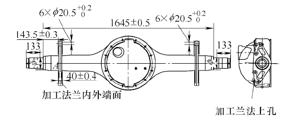
Figure 1 axle structure
Overall layout of equipment structure
As shown in Fig. 2, the machine tool adopts an integrally cast bed, and the bed is inclined forward by 45°. The guide rail has good rigidity and convenient chip evacuation. The machine tool adopts the intermediate drive. The spindle box is placed in the middle of the bed. The workpiece is rotated by the vehicle and has the spindle C-axis stop function to achieve precise positioning of the workpiece in the circumferential direction. There is a tailstock and a servo power at each end of the bed. The tool holder and the servo power tool holder are mounted on the cross slide, and the slide plate is controlled by a numerical control system to perform movement of the X-axis and the Z-axis. The servo-powered tool holder can be used for drilling and milling keyway; the tailstock adopts the machine tool spindle structure to enhance its rigidity, and supports the workpiece through the tip to ensure high coaxiality at both ends of the workpiece; the left and right tool holders pass the servo motor and Ball screw drive can realize two-coordinate linkage for machining outer circle, end face, conical surface, arc surface and thread; left and right tool holders simultaneously process both ends of the workpiece to improve production efficiency. The electrical control system uses the FUNAC-0i-TD system. The headstock is lubricated with a lubrication pump, and the guide rails are lubricated with a centralized automatic lubrication pump.
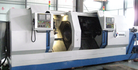
Figure 2 CNC double-head turning and milling composite processing equipment
Main specifications of machine tools
Spindle hole diameter: 600mm; the distance from the center of the spindle to the guide surface of the bed is 450mm; the maximum diameter on the bed rail: 800mm; the center of the spindle is 1200mm; the length of the workpiece is 200~2400mm; the length of the workpiece is 1500~2400mm; The speed is stepless speed regulation; the maximum speed of the spindle is 500r/min; the maximum fast moving speed: 15m/min in the longitudinal direction and 15m/min in the horizontal direction; the maximum stroke: the left and right tool holders are 700mm, 1050mm, and the horizontal left and right knives respectively The frame is 270mm; the surface roughness value Ra = 1.6μm; economic processing accuracy: IT6. Compared with traditional equipment, the machining accuracy is significantly improved, and the combined machining also greatly improves the machining efficiency.
Position clamping and transmission of workpiece
(1) Positioning and clamping of the workpiece The two ends of the workpiece are positioned in a 60° chamfering angle. The two top ends are installed in the sleeve taper holes of the left and right tails, and the workpiece is pressed by the hydraulic pressure. The hydraulic clamping force can be adjusted to avoid clamping deformation of the workpiece. The left tail stage can be manually adjusted to accommodate the machining of bridges of different lengths; the right tail stage hydraulic drive moves left and right to clamp or loosen the workpiece.
(2) Vehicle The spindle is connected to the workpiece through the vehicle to drive the workpiece to rotate. First, the vehicle is placed in the workpiece boring according to the position shown in Figure 3. Then, the vehicle positioning mechanism rotates clockwise. After tightening, the vehicle and the workpiece are locked by the hook plate. Finally, the workpiece is hoisted to the machine tool, and the quick-change joint on the vehicle is inserted into the protruding block of the end of the spindle sleeve of the machine tool, and the spindle sleeve drives the workpiece to rotate.
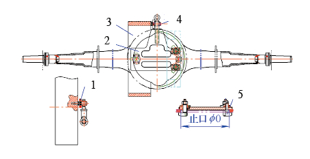
Figure 3 Schematic diagram of the vehicle
1. Quick change plug 2. Vehicle 3. Intermediate drive spindle sleeve 4. Joint bearing 5. Clamping plate
Specific processing techniques and steps
The position cloth cutter is shown in Figure 4. Station 4: rough outer circle and end face, finishing allowance 0.4mm; station 3: grooving; station 2: outer circle and end face of finishing car; station 1: coarse and fine thread; station 9: thick Finishing the outer end of the flange; station 7: inner end of the car flange; station 6: 12.3mm × 26mm keyway at both ends of the milling; station 5: drilling 6-φ20.5mm hole (12 holes at both ends) ).
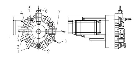
Figure 4 station cloth knife
1. Thread 2. Fine outer circle and end face 3. Grooving tool 4. Rough outer circle and end face
5. Drilling "U" drill 6. Milling keyway 7. Inner end of the car flange 8. Probe 9. Extruding the outer end of the flange
Determination of the location of the hole
After the workpiece is installed, the position is the original zero point of the C axis of the machine tool. Due to the error caused by the individual differences of the workpiece, the position of the initial machining hole of the part (see Figure 5) cannot be set to coincide with the zero point of the C axis. The distance between the position and the edge of the contour will be uneven.
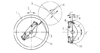
Figure 5 Schematic diagram of the measurement principle
1. Drive spindle (C axis) 2. C axis movement direction 3. X axis direction 4. X axis origin
5. Infrared probe 6. Machining the workpiece 7. Rotation axis of the workpiece 8. Hole position 1 9, 10. Measuring point
In order to rotate the workpiece to the correct position to be machined, an in-line inspection device is installed. The detection method is as follows:
The moving parts of the machine tool return to zero. Rotate the tool holder to the probe station, and move the Z-direction and X-direction of the knife holder slide to the set position. The intermediate drive spindle (C axis) of the machine tool rotates the workpiece so that one side of the contour of the workpiece contacts the probe. At this time, the C axis rotation stops, and the system records the measurement data to variable 1. Then the C-axis is rotated in the opposite direction so that the other side of the contour of the workpiece comes into contact with the probe, and the C-axis stops rotating. The system records the measurement data to variable 2. That is, the measurement work is completed, and after calculation by the numerical control system, the initial hole position suitable for the workpiece can be obtained.
At this point, the knife holder slide can be retracted to a safe position and the tool holder is rotated to the drilling station. The Z-direction and X-direction of the knife holder slide to the set position in sequence. The system calculates the data by the built-in macro program, and drives the workpiece to rotate to the initial machining hole of the part (hole position 1), which can be drilled. In addition, the keyway to be machined has no phase requirements on the circumference and can be machined in any direction.
Conclusion
This equipment completes the turning, drilling and milling process of the shaft end of the axle housing at one time. The dimensional accuracy of the workpiece processing and the positional accuracy of the hole completely meet the requirements of the user.
Color Flakes,Epoxy Acrylic Chips,Multi-Color Rock-Chips,Decorative Acrylic Flakes
Jiangxi Tiansheng New Materials Co.,Ltd , https://www.jx-tis.com