Acrel-6000/B Electrical Fire Monitoring System, Huaihua High-speed Railway South Station Front Square, Jiangsu Anke Rui Electrical Manufacturing Co., Ltd., Jiangyin, Jiangsu 214405, China
Abstract: This paper briefly describes the composition principle of the electrical fire monitoring system, and analyzes the design basis and related specifications of the electrical fire monitoring system in the application. Finally, through the introduction of Ankerui residual current electric fire monitoring system in the electric fire monitoring system project of the front square of Huaihua High-speed Railway South Station, the realization of the function of the electric fire monitoring system and its significance are expounded.
Key words: electrical fire; monitoring system; Acrel-6000/Q; Huaihua High-speed Railway South Station;
0 Overview Huaihua High-speed Railway South Station Front Square is located at the east side of the southern end of Hutian South Avenue, Hecheng District, Huaihua City, Hunan Province - Gaochun South Railway Station, Huaihua City, Gaochun Road. The project has 2 floors above ground and 2 underground floors. The underground two floors are 4.5 meters high, and the underground floor is 5.5 meters high (partial 6 meters, 6.5 meters). The floor height is 4.5 meters and the second floor is 4.5 meters high. The total construction area is 98,800 m2; the above-ground construction area is 4000 m2; the underground construction area is 94,800 m2. The construction height is 12 m.
This project is 449 ARCM200 series instruments in the distribution room and floor distribution box of the front square of Huaihua High-speed Railway South Station. The project is mainly responsible for monitoring the leakage status of the low-voltage outlets distributed in the distribution room and the distribution box, and promptly reminding the duty-keeping personnel in the control room to prevent the occurrence of electrical fires.
There are 449 ARCM200s in the front square of Huaihua High-speed Railway South Station installed in the distribution room and floor distribution box. The field instrument adopts the bus mode to access the distribution indoor communication collection box, and then uploads the data to the Acrel-6000/Q piano desktop electrical fire monitoring system of the control center through the optical fiber.
1 Reference Standards In recent years, in order to increase the intensity of electrical fire monitoring and prevention, the state has successively formulated or revised a number of relevant standards and regulations to strengthen the prevention of electrical fires. There are:
1.1.GB50045-95 (2005 edition) "High-rise civil building design fire protection code", which stipulates in clause 9.5.1: high-rise buildings should be equipped with leakage fire alarm system in places with high fire risk and dense personnel.
1.2.GB50016-2006 "Code for Fire Protection of Building Design", as specified in Article 11.2.7: The following places should be equipped with residual current action electrical fire monitoring system. These venues include various types of theaters, galleries, warehouses, residential communities, hospitals, shops, schools, and more.
1.3. The relevant provisions of the national standard "Building electrical fire prevention requirements and testing methods" also clearly require that "the residual current action protector that automatically cuts off the power or alarm should be set at the power incoming end".
1.4. The products of the electrical fire monitoring system shall meet: GB14287.1-2005 "Electrical Fire Monitoring Equipment", GB14287.2-2005 "Residual Current Electric Fire Monitoring Detector", GB14287.3-2005 "Warming Electrical Fire" Monitoring detector
1.5. Installation and operation of electrical fire monitoring system should meet GB13955-2005 "Residual current action protection device installation and operation"
1.6. The power supply of the electrical fire monitoring system shall meet the requirements of GB50052 "Design Specification for Power Supply and Distribution System". 1.7. The design of the electrical fire monitoring system shall meet the requirements of the "Design Method of Electrical Fire Monitoring System" (Interim Provisions)
2 System Composition Huaihua High-speed Railway South Station Front Square Electrical Fire Project consists of electrical fire monitoring background, electrical fire detector and leakage current transformer.
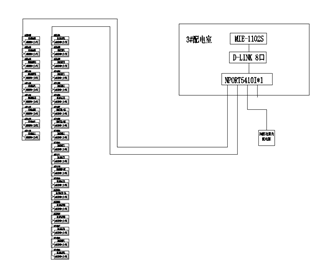
The communication bus of this project has a total of 20 communication buses. After the bus is connected hand in hand in the power distribution room and the floor distribution box, it is connected to the collection box in the power distribution room, and the data is uploaded to the background through the optical fiber to form an electrical fire system. aorta. The leakage current transformer in the cabinet is connected to the leakage detector through the current line, and the leakage detector displays the leakage condition in real time. The above describes a set of electrical fire monitoring systems with stable signal and reliable accuracy. The system networking is divided into three layers:
1) Station control management station management The management personnel for the electrical fire monitoring system are the direct window of human-computer interaction and the uppermost part of the system. Mainly composed of system software and necessary hardware equipment, such as touch screen, UPS power supply and so on. The monitoring system software calculates, analyzes, and processes various types of data information on the site, and responds to the on-site transportation situation by means of graphics, digital display, sound, and indicator lights.
Monitoring host: used for data collection, processing, and data forwarding. Provides data interfaces for system management, maintenance, and analysis within and outside the system.
UPS: Ensure the normal power supply of the computer monitoring system, and ensure the normal operation of the station management management equipment when the whole system has power supply problems.
The background monitoring device is set in the control room.
2) Network communication layer communication medium: The system mainly adopts shielded twisted pair cable, realizes real-time communication between field device and host computer by RS485 interface and MODBUS communication protocol.
3) Field equipment layer The field equipment layer is a data acquisition terminal, mainly for the ARCM200 series residual electrical fire monitoring detector.
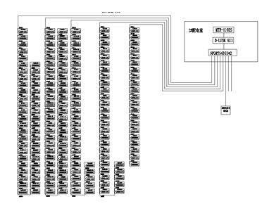
The system structure topology is as follows:
3 electrical fire equipment 3.1, Acrel-6000 electrical fire monitoring background:
The main technical parameters of the power supply:
1 rated working voltage AC220V (-15% ~ +10%)
2 standby power supply: When the main power supply is under voltage or power failure, maintain the monitoring equipment working time ≥ 4 hours working system:
24-hour work communication method:
RS485 bus communication, Modbus-RTU communication protocol, transmission distance of 1km, the communication transmission distance monitoring capacity can be extended by repeater:
1 monitoring equipment can monitor up to 200 monitoring units (detectors)
2 can be equipped with ARCM series monitoring detector monitoring alarm items:
1 residual current fault (leakage): fault unit attribute (part, type)
2 temperature alarm (over temperature): fault unit attribute (part, type)
3 current fault (overcurrent): fault unit attribute (part, type)
Monitoring alarm response time: ≤30s
Monitoring alarm sound pressure level (A weighting): ≥70dB/1m
Monitoring alarm light display: red LED indicator, red light alarm signal should be maintained until manual reset monitoring alarm sound signal: can be manually eliminated, when there is alarm signal input again, the fault alarm item can be started again:
1 The communication cable between the monitoring device and the detector is disconnected or short-circuited. 2 The monitoring device main power supply is under voltage or power-off. 3 The connection between the charger and the battery charging the battery is broken or short-circuited. The alarm response time is ≤ 100s
Monitoring alarm sound pressure level (A weighting): ≥70dB/1m
Monitoring alarm light display: yellow LED indicator, yellow light alarm signal should be maintained until the fault alarm sound signal: can be manually eliminated, when there is alarm signal input again, can start the fault again, the normal operation of the non-fault loop is not Affect control output:
Alarm control output: 1 set of normally open passive contacts, capacity: AC250V3A or DC30V3A
Self-test items:
1 indicator check: alarm, fault, operation, main power, standby power indicator 2 display check 3 audio device check self-test time ≤ 60s
record:
1 Record content: record type, occurrence time, detector number, area, fault description, can store no less than 20,000 records 2 record query: query operation rating according to the date and type of record:
1 Daily duty class: real-time status monitoring, event record query 2 monitoring operation level: real-time status monitoring, event record query, detector remote reset, device self-test 3 system management level: real-time status monitoring, event record query, detector remote reset , equipment self-test, monitoring equipment system parameter query, monitoring equipment module detection, operator add and delete use environmental conditions:
1Workplace: Fire control room, manned substation (distribution room), on-board room on duty 2 Working environment temperature: 0°C~40°C
3 working environment relative humidity: 5% ~ 95% RH
4 altitude: ≤ 2500m
3.2. ARCM200 series instrument ARCM200 residual current type electric fire monitoring detector is designed for TT and TN systems below 0.4kV. It passes the fire risk parameters such as residual current, wire temperature, over current and over voltage of the distribution circuit. Implementation of monitoring and management to prevent electrical fires, and real-time monitoring of a variety of power parameters to provide accurate data for energy management. The product adopts advanced microcontroller technology, with high integration, small size, convenient installation, intelligent, digital and networked. It is an ideal choice for building electrical fire prevention monitoring and system insulation aging prediction. The product complies with the standard requirements of GB14287.2-2005 "Electrical Fire Monitoring System Part 2: Residual Current Electrical Fire Monitoring Detector".
4 system function 4.1. monitoring alarm function:
The monitoring equipment can receive the leakage and temperature information of multiple detectors, and emit an audible and visual alarm signal when the alarm occurs. At the same time, the red “alarm†indicator on the device lights up, the display indicates the alarm location and alarm type, and the alarm time is recorded. The sound and light alarm is always maintained. Until the display is reset by pressing the display "Reset" button. The audible alarm signal can also be manually removed using the display "Muffler" button.
4.2. Fault alarm function Communication fault alarm: When a communication fault occurs between the monitoring device and any of the connected detectors, the corresponding detector in the monitoring screen displays a fault prompt, and the yellow “fault†indicator on the device lights up. And a fault alarm sound is issued.
Power failure alarm: When the main power or backup power fails, the monitoring device also emits an audible and visual alarm signal and displays the fault information. You can enter the corresponding interface to view the detailed information and release the alarm sound.
4.3. Self-test function Check whether all status indicators, display screens and speakers in the device are normal.
4.4. Alarm record storage query function When leakage, over-temperature alarm or communication or power failure occurs, the alarm part, fault information, alarm time and other information are stored in the database. When the alarm is released and the fault is eliminated, the same is recorded. Historical data provides a variety of convenient and fast ways to query.
4.5. Power Function When the main power supply has a power failure or undervoltage fault, the monitoring equipment can automatically switch to the standby power supply. When the main power supply returns to normal power supply, it will automatically switch back to the main power supply. During the switching process, the monitoring equipment will run continuously and smoothly.
4.6. The detector control function can be remotely reset controlled by all the detectors connected to the device through the monitoring software operation.
4.7. Authority Control Function To ensure the safe operation of the monitoring system, the monitoring device software operation authority is divided into three levels, and different levels of operators have different operation rights.
5 Conclusion Huaihua High-speed Railway South Station front square electrical fire monitoring system consists of electrical fire monitoring device Acrel-6000/Q, leakage fire detector leakage fire detector ARCM200. The Acrel-6000 electrical fire monitoring system is an industrial grade that is independently developed by the company to receive field devices such as residual current electrical fire detectors to achieve alarm, monitoring, control, and management of protected electrical circuits. Hardware/software system. The system is applied to fire control centers in large shopping malls, living quarters, production bases, office buildings, shopping malls, hospitals, etc., and telemetry, remote adjustment, remote control, and remote signaling of detectors dispersed in the building are convenient for monitoring and control. management. The system uses a standard Modbus field bus to connect detectors with communication functions. When the detected parameter in the field protection circuit exceeds the alarm set value, it can send out alarm signals and control signals, can indicate the alarm part and save the alarm. information. The field instrument is connected to the Acrel-6000/Q piano electrical fire monitoring system of the control center by bus. The system has the advantages of convenient installation and transportation, high cost performance and convenient maintenance.
References [1]. Ren Zhicheng Zhou Zhong. Principles and Application Guidelines of Digital Meters for Electric Power Measurement [M]. Beijing. China Electric Power Press.2007.4
[2]. Zhou Zhong. Application of power meter in electric energy sub-metering of large public buildings [J]. Modern Building Electric 2010.6
About the Author:
Zhou Jie female, undergraduate, Jiangsu Ankerui Electric Manufacturing Co., Ltd., the main research direction is smart grid power supply and distribution
Abstract: This paper briefly describes the composition principle of the electrical fire monitoring system, and analyzes the design basis and related specifications of the electrical fire monitoring system in the application. Finally, through the introduction of Ankerui residual current electric fire monitoring system in the electric fire monitoring system project of the front square of Huaihua High-speed Railway South Station, the realization of the function of the electric fire monitoring system and its significance are expounded.
Key words: electrical fire; monitoring system; Acrel-6000/Q; Huaihua High-speed Railway South Station;
0 Overview Huaihua High-speed Railway South Station Front Square is located at the east side of the southern end of Hutian South Avenue, Hecheng District, Huaihua City, Hunan Province - Gaochun South Railway Station, Huaihua City, Gaochun Road. The project has 2 floors above ground and 2 underground floors. The underground two floors are 4.5 meters high, and the underground floor is 5.5 meters high (partial 6 meters, 6.5 meters). The floor height is 4.5 meters and the second floor is 4.5 meters high. The total construction area is 98,800 m2; the above-ground construction area is 4000 m2; the underground construction area is 94,800 m2. The construction height is 12 m.
This project is 449 ARCM200 series instruments in the distribution room and floor distribution box of the front square of Huaihua High-speed Railway South Station. The project is mainly responsible for monitoring the leakage status of the low-voltage outlets distributed in the distribution room and the distribution box, and promptly reminding the duty-keeping personnel in the control room to prevent the occurrence of electrical fires.
There are 449 ARCM200s in the front square of Huaihua High-speed Railway South Station installed in the distribution room and floor distribution box. The field instrument adopts the bus mode to access the distribution indoor communication collection box, and then uploads the data to the Acrel-6000/Q piano desktop electrical fire monitoring system of the control center through the optical fiber.
1 Reference Standards In recent years, in order to increase the intensity of electrical fire monitoring and prevention, the state has successively formulated or revised a number of relevant standards and regulations to strengthen the prevention of electrical fires. There are:
1.1.GB50045-95 (2005 edition) "High-rise civil building design fire protection code", which stipulates in clause 9.5.1: high-rise buildings should be equipped with leakage fire alarm system in places with high fire risk and dense personnel.
1.2.GB50016-2006 "Code for Fire Protection of Building Design", as specified in Article 11.2.7: The following places should be equipped with residual current action electrical fire monitoring system. These venues include various types of theaters, galleries, warehouses, residential communities, hospitals, shops, schools, and more.
1.3. The relevant provisions of the national standard "Building electrical fire prevention requirements and testing methods" also clearly require that "the residual current action protector that automatically cuts off the power or alarm should be set at the power incoming end".
1.4. The products of the electrical fire monitoring system shall meet: GB14287.1-2005 "Electrical Fire Monitoring Equipment", GB14287.2-2005 "Residual Current Electric Fire Monitoring Detector", GB14287.3-2005 "Warming Electrical Fire" Monitoring detector
1.5. Installation and operation of electrical fire monitoring system should meet GB13955-2005 "Residual current action protection device installation and operation"
1.6. The power supply of the electrical fire monitoring system shall meet the requirements of GB50052 "Design Specification for Power Supply and Distribution System". 1.7. The design of the electrical fire monitoring system shall meet the requirements of the "Design Method of Electrical Fire Monitoring System" (Interim Provisions)
2 System Composition Huaihua High-speed Railway South Station Front Square Electrical Fire Project consists of electrical fire monitoring background, electrical fire detector and leakage current transformer.
The communication bus of this project has a total of 20 communication buses. After the bus is connected hand in hand in the power distribution room and the floor distribution box, it is connected to the collection box in the power distribution room, and the data is uploaded to the background through the optical fiber to form an electrical fire system. aorta. The leakage current transformer in the cabinet is connected to the leakage detector through the current line, and the leakage detector displays the leakage condition in real time. The above describes a set of electrical fire monitoring systems with stable signal and reliable accuracy. The system networking is divided into three layers:
1) Station control management station management The management personnel for the electrical fire monitoring system are the direct window of human-computer interaction and the uppermost part of the system. Mainly composed of system software and necessary hardware equipment, such as touch screen, UPS power supply and so on. The monitoring system software calculates, analyzes, and processes various types of data information on the site, and responds to the on-site transportation situation by means of graphics, digital display, sound, and indicator lights.
Monitoring host: used for data collection, processing, and data forwarding. Provides data interfaces for system management, maintenance, and analysis within and outside the system.
UPS: Ensure the normal power supply of the computer monitoring system, and ensure the normal operation of the station management management equipment when the whole system has power supply problems.
The background monitoring device is set in the control room.
2) Network communication layer communication medium: The system mainly adopts shielded twisted pair cable, realizes real-time communication between field device and host computer by RS485 interface and MODBUS communication protocol.
3) Field equipment layer The field equipment layer is a data acquisition terminal, mainly for the ARCM200 series residual electrical fire monitoring detector.
The system structure topology is as follows:

3 electrical fire equipment 3.1, Acrel-6000 electrical fire monitoring background:
The main technical parameters of the power supply:
1 rated working voltage AC220V (-15% ~ +10%)
2 standby power supply: When the main power supply is under voltage or power failure, maintain the monitoring equipment working time ≥ 4 hours working system:
24-hour work communication method:
RS485 bus communication, Modbus-RTU communication protocol, transmission distance of 1km, the communication transmission distance monitoring capacity can be extended by repeater:
1 monitoring equipment can monitor up to 200 monitoring units (detectors)
2 can be equipped with ARCM series monitoring detector monitoring alarm items:
1 residual current fault (leakage): fault unit attribute (part, type)
2 temperature alarm (over temperature): fault unit attribute (part, type)
3 current fault (overcurrent): fault unit attribute (part, type)
Monitoring alarm response time: ≤30s
Monitoring alarm sound pressure level (A weighting): ≥70dB/1m
Monitoring alarm light display: red LED indicator, red light alarm signal should be maintained until manual reset monitoring alarm sound signal: can be manually eliminated, when there is alarm signal input again, the fault alarm item can be started again:
1 The communication cable between the monitoring device and the detector is disconnected or short-circuited. 2 The monitoring device main power supply is under voltage or power-off. 3 The connection between the charger and the battery charging the battery is broken or short-circuited. The alarm response time is ≤ 100s
Monitoring alarm sound pressure level (A weighting): ≥70dB/1m
Monitoring alarm light display: yellow LED indicator, yellow light alarm signal should be maintained until the fault alarm sound signal: can be manually eliminated, when there is alarm signal input again, can start the fault again, the normal operation of the non-fault loop is not Affect control output:
Alarm control output: 1 set of normally open passive contacts, capacity: AC250V3A or DC30V3A
Self-test items:
1 indicator check: alarm, fault, operation, main power, standby power indicator 2 display check 3 audio device check self-test time ≤ 60s
record:
1 Record content: record type, occurrence time, detector number, area, fault description, can store no less than 20,000 records 2 record query: query operation rating according to the date and type of record:
1 Daily duty class: real-time status monitoring, event record query 2 monitoring operation level: real-time status monitoring, event record query, detector remote reset, device self-test 3 system management level: real-time status monitoring, event record query, detector remote reset , equipment self-test, monitoring equipment system parameter query, monitoring equipment module detection, operator add and delete use environmental conditions:
1Workplace: Fire control room, manned substation (distribution room), on-board room on duty 2 Working environment temperature: 0°C~40°C
3 working environment relative humidity: 5% ~ 95% RH
4 altitude: ≤ 2500m
3.2. ARCM200 series instrument ARCM200 residual current type electric fire monitoring detector is designed for TT and TN systems below 0.4kV. It passes the fire risk parameters such as residual current, wire temperature, over current and over voltage of the distribution circuit. Implementation of monitoring and management to prevent electrical fires, and real-time monitoring of a variety of power parameters to provide accurate data for energy management. The product adopts advanced microcontroller technology, with high integration, small size, convenient installation, intelligent, digital and networked. It is an ideal choice for building electrical fire prevention monitoring and system insulation aging prediction. The product complies with the standard requirements of GB14287.2-2005 "Electrical Fire Monitoring System Part 2: Residual Current Electrical Fire Monitoring Detector".
4 system function 4.1. monitoring alarm function:
The monitoring equipment can receive the leakage and temperature information of multiple detectors, and emit an audible and visual alarm signal when the alarm occurs. At the same time, the red “alarm†indicator on the device lights up, the display indicates the alarm location and alarm type, and the alarm time is recorded. The sound and light alarm is always maintained. Until the display is reset by pressing the display "Reset" button. The audible alarm signal can also be manually removed using the display "Muffler" button.
4.2. Fault alarm function Communication fault alarm: When a communication fault occurs between the monitoring device and any of the connected detectors, the corresponding detector in the monitoring screen displays a fault prompt, and the yellow “fault†indicator on the device lights up. And a fault alarm sound is issued.
Power failure alarm: When the main power or backup power fails, the monitoring device also emits an audible and visual alarm signal and displays the fault information. You can enter the corresponding interface to view the detailed information and release the alarm sound.
4.3. Self-test function Check whether all status indicators, display screens and speakers in the device are normal.
4.4. Alarm record storage query function When leakage, over-temperature alarm or communication or power failure occurs, the alarm part, fault information, alarm time and other information are stored in the database. When the alarm is released and the fault is eliminated, the same is recorded. Historical data provides a variety of convenient and fast ways to query.
4.5. Power Function When the main power supply has a power failure or undervoltage fault, the monitoring equipment can automatically switch to the standby power supply. When the main power supply returns to normal power supply, it will automatically switch back to the main power supply. During the switching process, the monitoring equipment will run continuously and smoothly.
4.6. The detector control function can be remotely reset controlled by all the detectors connected to the device through the monitoring software operation.
4.7. Authority Control Function To ensure the safe operation of the monitoring system, the monitoring device software operation authority is divided into three levels, and different levels of operators have different operation rights.
5 Conclusion Huaihua High-speed Railway South Station front square electrical fire monitoring system consists of electrical fire monitoring device Acrel-6000/Q, leakage fire detector leakage fire detector ARCM200. The Acrel-6000 electrical fire monitoring system is an industrial grade that is independently developed by the company to receive field devices such as residual current electrical fire detectors to achieve alarm, monitoring, control, and management of protected electrical circuits. Hardware/software system. The system is applied to fire control centers in large shopping malls, living quarters, production bases, office buildings, shopping malls, hospitals, etc., and telemetry, remote adjustment, remote control, and remote signaling of detectors dispersed in the building are convenient for monitoring and control. management. The system uses a standard Modbus field bus to connect detectors with communication functions. When the detected parameter in the field protection circuit exceeds the alarm set value, it can send out alarm signals and control signals, can indicate the alarm part and save the alarm. information. The field instrument is connected to the Acrel-6000/Q piano electrical fire monitoring system of the control center by bus. The system has the advantages of convenient installation and transportation, high cost performance and convenient maintenance.
References [1]. Ren Zhicheng Zhou Zhong. Principles and Application Guidelines of Digital Meters for Electric Power Measurement [M]. Beijing. China Electric Power Press.2007.4
[2]. Zhou Zhong. Application of power meter in electric energy sub-metering of large public buildings [J]. Modern Building Electric 2010.6
About the Author:
Zhou Jie female, undergraduate, Jiangsu Ankerui Electric Manufacturing Co., Ltd., the main research direction is smart grid power supply and distribution
Mitre Saw is a professional tool that is suitable for cutting at a variety of angles. The saw has a blade mounted on a swing arm that pivots left or right to produce angled cuts. You can use a miter saw to quickly make cuts for crown molding, picture frames, door frames, window casings and more. There are several types of miter saws: compound miter saw, dual compound miter saw, and sliding compound miter saw.
Mitre Saw
Mitre Saw,Craftsman Miter Saw,Electric Mitre Saw,Sliding Miter Saw
AWLOP CO.,LTD , https://www.awlop.com