First, the engine and the aircraft
1. Engine type
1) Turbojet engine (WP) WP5, WP6, WP7, ... WP13
2) Turboprop (WJ) WJ5, WJ6, WJ7
3) Turbofan engine (WS) WS9, WS10, WS11
4) Turbine shaft engine (WZ) WZ5, WZ6, WZ8, WZ9
5) Piston engine (HS) HS5, HS6, HS9
2. Engine structure and composition
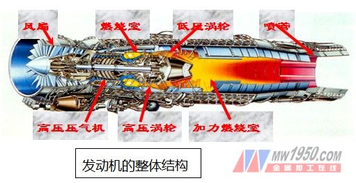
Gas turbine engines are mainly composed of three major components: compressor, combustion and turbine, as well as fuel system, oil system, air system, electrical system, intake and exhaust system and bearing force transmission system. (The overall structure of the engine is shown in Figure 1 below.) The compressor and turbine except for combustion in the three major components are composed of a rotor and a stator. The stator consists of inner and outer casings and guide (rectified) blades; the rotor is made up of blade discs and shafts. And bearing composition, in which the number of blades is the most (see Tables 1-5)
3. Engine working principle and heat treatment process
Working principle: The engine will burn a large amount of fuel to generate thermal energy. The potential energy will expand into the oblique incision of the turbine guide to generate a large amount of kinetic energy. A part of it will be converted into mechanical work to drive the compressor and accessories, and the remaining energy can be accelerated by the tail nozzle to generate thrust.
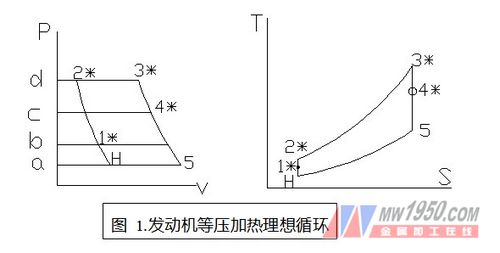
Thermal process: Use the p-Ï… or TS diagram to represent the thermal process of the engine:
4. Aircraft and engine
The engine is the power of the aircraft and the heart of the aircraft. Different types of aircraft are equipped with different types of engines. Such as:
1) Military and civilian transport aircraft, bombers, passenger aircraft, and WJ, WS, WP engines.
2) Strong fighters, fighters, trainers, reconnaissance aircraft, and WP, ​​WS, and HS engines.
3) Military and civilian helicopters are equipped with WZ engines.
Second, the blade
In gas turbine engines, the blades are the largest number of compressor blades or turbine blades, and the engine relies on the numerous blades to complete the compression and expansion of the gas and generate powerful power with the highest efficiency to push the aircraft forward. . The blade is a special kind of part. It has a large number, complicated shape, high requirements, difficult processing, and is a faulty part. It has always been the key to the production of various engine factories, so the human, material and financial resources invested in it. Both are relatively large, and domestic and foreign engine manufacturers are using the best efforts to improve the performance of the blade, production capacity and quality to meet the needs.
1. Why do the blades have to be twisted?
In the flow channel, since the peripheral velocities are different at different radii, the angle of attack of the airflow differs greatly in different radii element levels, and at the tip of the blade, the maximum circumferential speed is caused, resulting in a large frontal attack. The result is a severe airflow separation at the leaf-leaf back; at the blade root, a large negative angle of attack due to the smallest circumferential velocity results in severe airflow separation of the leaf-shaped basin. Therefore, for straight blades. Except for the recent work of a part of the middle diameter, the rest will cause serious air separation, that is to say, the compressor or turbine working with straight blades is extremely inefficient and even reaches a point where it is impossible to operate at all. .
The number of engine blades is counted as follows (take WJ6 and WS11 as examples):
1.WJ6
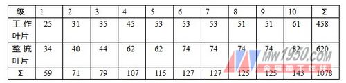
The number of compressor blades is shown in Table 1. Table 1
The number of turbine blades is shown in Table 2. Table 2
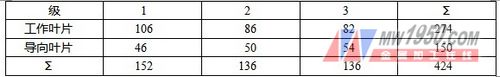
Total number of engine blades
1078+424=1502
1502×500=751000
According to the average price of 500 yuan / piece, the total output value of 375.5 million
2.WS11
The total number of compressor blades is shown in Table 3.
table 3
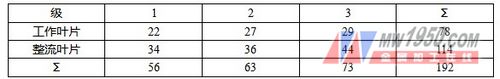
The number of fan blades is shown in Table 4.
Table 4
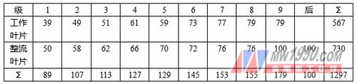
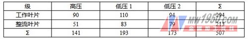
The number of turbine blades is shown in Table 5.
table 5
Total number of blades
1297+192+507=1996
According to 300 units
2000×300=600000 pieces
Priced at 500 yuan / piece
The total output value is 300 million yuan.
2. How the blade works
1) Compressor blades
As the name implies, the compressor is used to “pressurize†the pressure required to press the inlet atmospheric pressure PH=1 to the outlet. We will analyze the principle of compression as shown below:
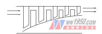
Figure 2 Compressor flow to
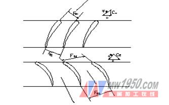
Figure 3 Primitive level leaf fence channel
The gas in the flow channel of Figure 2 is "squeezing" the pressure of the gas due to its smaller and smaller volume. In Figure 2, due to the expansion of the cross-sectional area in the relative motion in the cascade channel, the speed is reduced, ω1>ω2, the kinetic energy of the airflow is reduced, and the reduced kinetic energy is mostly converted into the pressure energy of the airflow, thereby increasing the pressure of the airflow P1> P2. The task of the work wheel is not only to increase the pressure, but also to continuously give the air flow if the rim work Lu constantly compresses the air flow. There are working blades and rectifying blades in the compressor blades. The working blades rotate with the rotor, and the rectifying blades are stationary. The airflow of the working blade inlet or outlet is disordered to make the flow of the air flow orderly to reduce the flow loss. . The air flow is also a supercharging process in the rectifying blades.
There are many stages in the number of compressors. This is because its stage pressure ratio is not high, generally around 1.2. To increase the air pressure to a high level, many stages are required. The relationship between the total pressure ratio and the stage pressure ratio is πn*=πnIπKIIπKIII...πKn
The number of compressor stages is generally 8 or higher.
2) Turbine blades
Analyze the working principle of turbine blades through the structural flow of the turbine and the structural pattern of the elementary blade cascade
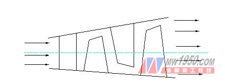
Figure 4 Turbine flow channel

Figure 5 Turbine Primer Cascade Channel
It can be seen from Fig. 3 and Fig. 2 that the state of the airflow inlet and outlet is reversed. As the airflow flows through the flow path of Figure 3, the pressure is getting lower due to the larger area. This is due to the volume required for the airflow to flow through the cascade channels F1CA and F2PK during which the pressure drops rapidly.
Flashlight,Flashlight Screwdriver,Best Flashlight,Flashlight For Sale
Hangzhou Fantasy Technology Co.,ltd , https://www.ledluxlite.com