The machining accuracy requirements are now getting higher and higher, especially in the field of five-axis machining. Some complex parts require the machine to maintain high precision and repeat positioning accuracy during long machining operations. For the five-axis machine tool processing, due to the influence of external environmental temperature changes and the accuracy of the machine itself (such as collision, replacement of major moving parts, etc.), the motion characteristic model saved in the numerical control system is different from the actual motion characteristics of the machine tool (see the figure). 1) When positioning the rotary axis, these differences will cause the workpiece to be processed with low precision. Therefore, in actual machining, especially when finishing, it is necessary to calibrate the five-axis accuracy to improve the machining accuracy of the machine tool.
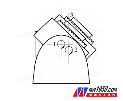
Figure 1 Motion characteristics model saved in the CNC system
1. Traditional five-axis accuracy calibration method
The traditional five-axis head calibration method requires a dedicated technician to measure the mechanical eccentricity of the rotating shaft by a specific method using a dedicated measuring tool such as a standard inspection mandrel, a dial gauge, a measuring probe, and the like. Taking the fork type rotating head (C, A axis) as an example, it is necessary to correct the eccentricity value of the spindle rotation center and the A-axis rotation center in the Y direction, the distance from the A-axis rotation center to the spindle nose, the C-axis rotation center and the spindle rotation center. Eccentricity values ​​in the X and Y directions, and so on. The following is a brief description of the manual calibration method by correcting the eccentricity of the spindle rotation center and the A-axis rotation center in the Y direction.
First install a standard test mandrel on the spindle, place the meter in the Z direction, position the A axis at -90°, and adjust the scale on the meter to 0 (see Figure 2), then rotate A to +90°. Read the value on the measurement table (see Figure 3), divide the value by 2 and enter the compensation value into the system parameter MP7530.1. Retest the calibration until the accuracy requirement is reached.
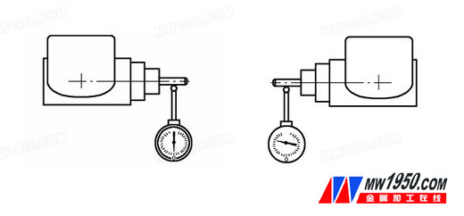
Fig. 2 Actual motion characteristics of the machine toolFig. 3 Deviation of workpiece rotation positioning
Therefore, if the traditional detection method is used, not only the technical personnel are required to be high, but also the method is relatively complicated, the test items are more, the time is long, the measurement accuracy is not easy to be guaranteed, and the processing efficiency and precision of the machine tool are affected.
Solar Flood Light,Best Solar Flood Lights,Best Solar Security Light,Best Outdoor Solar Flood Lights
Zhongshan Tiger Lighting Co.,Ltd. , https://www.tigerstreetlight.com