1. The concept of a layer
The CAXA electronic drawing system, like other CAD drawing systems, provides users with layer functionality. Layers are an indispensable software environment for structured design. As we all know, a mechanical engineering drawing contains a variety of information, geometric information to determine the shape of the figure, non-geometric information indicating attributes such as line type, color, and various sizes and symbols. So much content is concentrated on one drawing, which inevitably puts a lot of burden on the design drawing work. If the relevant information can be grouped together, or a part or component can be drawn together or edited separately, and can be combined or separately extracted when needed, the drawing design work will be further simplified.
The layer can be thought of as a transparent sheet, and graphics and various information are drawn and stored on these transparent sheets. Up to 100 layers can be built in the CAXA electronic board, but each layer must have a unique layer name. Different lines and colors can be set on different layers. All the layers are uniformly positioned by the system, and the coordinate system is the same. Therefore, the graphics drawn on different layers will not be confused. The image of Figure 1 illustrates The concept of layers.
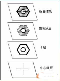
figure 1
1.1 Layer operation
According to the drawing needs, the corresponding layer state can be modified at any time by interacting with the dialog box, and operations such as setting the current layer, establishing a new layer, and modifying the layer state can be performed.
Command drop-down menu "Settings → Layer Control"; the property control bar middle control icon
The function operates on the layer, such as setting the current layer, modifying the layer name, creating layers, and so on.
After the operation control picks up the layer control icon in the property bar, the system pops up the layer control list box, as shown in the following figure. After selecting the desired item, press the "OK" button and the operation ends.
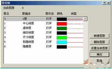
figure 2
The specific operation of the layer is as follows:
1) Set the current layer
Sets a layer to the current layer, and the subsequent drawn graphic elements are drawn on that layer. The system has only a single current layer, and the other layers are non-current layers. The so-called "current layer" is the layer that is currently operating. The current operation is performed on the current layer, so the current layer is also called the "active layer." In order to operate on a graphic in an existing layer, the layer must be placed as the current layer.
There are two ways to set the current layer:
(1) Set in the current layer drop-down list box
In the current layer drop-down list box shown in Figure 3, click the desired layer with the left mouse button to complete the setting operation of the current layer selection.
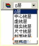
image 3
(2) Set in the layer control dialog
In the layer control dialog box shown in Figure 2, which layer is displayed in the upper layer, click the desired layer in the layer list of the dialog box, and then click the right side. The "Set Current Layer" button, click the "OK" button after the setting is completed.
Switch Alarm Flowmeter,Panel Flow Meter,Plate Flow Meter
Jiekelong Precision Manufacturing Co., Ltd. , http://www.nbcoupling.com