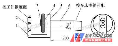
Figure 2 Schematic diagram of the eccentric clamp
1. Bending plate 2. Positioning taper hole 3. Bolt 4. Fastening nut 5. Disc 6. Positioning shaft
The positioning shaft 6 on the positioning portion of the clamp is machined from 45 steel. The rear end of the positioning shaft 6 is machined into a tapered surface that cooperates with the taper hole of the lathe spindle, which is the positioning reference of the entire clamp. The curved plate 1 on the workpiece positioning body is welded to the disc 5 after being welded by the steel plate. The bolt 3 is welded and fixed to the disc 5, and its axis is eccentric with the positioning shaft 6, and coincides with the axis of the workpiece after installation. Bolt 3 is a large pitch positive rotation thread, which is beneficial to the fast fastening and loosening of the workpiece. According to the effect in practical application, the single-line trapezoidal thread processed into 4mm pitch has the best effect, and has a fast screwing speed and lock. High tightening and long-lasting durability. A rounded surface having a large area at the front end of the tightening nut 4 is fitted with the bolt 3 to form a locking device for the workpiece. The positioning shaft 6 is welded to the disc 5 and has high coaxiality and perpendicularity requirements. The outer circumference of the turning disc 5 is rounded by the taper surface of the positioning shaft 6 after being centered in the taper hole of the lathe to adjust the precision of the inspection fixture each time the jig is installed. Two positioning taper holes are machined on the curved plate 1, and the outer circle of the tapered hole 2 and the circular disk 5 must be formed by positioning the tapered surface of the positioning shaft 6 and the taper surface of the lathe spindle once, so as to ensure the overall shape of the clamp. The lathe spindle has a high degree of concentricity. The eccentricity of the two positioning taper holes 2 is exactly the same as the eccentricity of the two cones of the workpiece 1, and the taper size is processed by the two-taper taper of the workpiece.
(2) Structure characteristics of locking device Conventional locking device is generally used to fasten the workpiece by pressing plate and bolt. It should be alternately rotated during operation. At least two nuts can clamp the workpiece. In practice, the workpiece is often clamped. The phenomenon of uneven holding force and pinching and pinching the workpiece, and the long adjustment and fastening time are not conducive to the improvement of production efficiency.
The locking device of the clamp described in this paper only uses a set of threading mechanism and has the following characteristics: 1 Both the bolt and the fastening nut adopt the positive-spindle trapezoidal thread, and the spiral direction is consistent with the normal rotation direction of the lathe spindle, due to inertia during the machining process. The force acts to make the workpiece turn tighter and tighter. 2 The workpiece and the two positioning taper holes are inserted into the tapered surface structure, and the more the workpiece moves forward, the tighter the structure is. This structure effectively prevents the unsafe factors of the workpiece from being loosened and the workpiece flying out during the machining process. 3 The front end of the fastening nut has a large circular plane and the surface of the workpiece forms a surface contact, which ensures the uniform pressing force and effectively protects the workpiece. 4 The workpiece shown in Figure 1 is an aluminum alloy casting with the characteristics of less cutting force required for machining, so the workpiece does not require a large locking force during machining. It has been proved by practice that during the operation and processing, the operator can tighten the hand with a little force to meet the requirements of cutting.
3. Application of the fixture
The rear tapered surface of the clamp positioning shaft 6 is accurately assembled in the taper hole of the lathe spindle, and the three claws of the three-jaw self-centering chuck clamp the outer circumference of the front end of the positioning shaft, and the positioning accuracy of the overall clamp is checked according to the disc 5 of the clamp. . Insert the two taper outer circles of the workpiece shown in Figure 1 into the two positioning taper holes of the fixture at the same time, and rotate the tightening nut 4 forward so that the end face is in contact with the workpiece end face and locked, and one of the inner holes of the workpiece And thread processing. After the machining is completed, loosen and turn the tightening nut 4 to move backwards. After the workpiece is separated from the taper hole of the clamp, rotate 180°, and insert another unprocessed workpiece cone into the positioning taper hole 2 to lock it and continue machining. This repeated operation completes the processing of the entire workpiece eccentric process.
4. Conclusion
The use of the special eccentric fixture effectively improves the production efficiency, ensures the product quality, and is particularly suitable for the production of a large number of product parts. It has been proved by production practice that the production efficiency of the fixture is greatly improved by 3 to 5 times compared with the conventional card loading method. Effectively guarantee product quality and greater business benefits.
Previous page
Economical Door,Melamine Door,Interior Door,Melamine Molded Door
Forest Bright Wood Industry Co., Ltd. , http://www.steeldoors-manufacturer.com